Wiring 4 HC-SR04 Ultrasonic Sensors + I2C LCD + Power LED to an Arduino Robot
Four HC-SR04 ultrasonic sensors each need two pins — trig and echo. An I²C LCD needs two more — SDA and SCL. Add a power LED, power, and ground connections for each sensor, and what looked like a simple wiring job turns into 12+ connections that all need to be right before anything works.
This post covers the wiring pass for the cardboard chassis robot: which pins every sensor goes to, where the I²C LCD connects on an Arduino Nano, how the sensors are physically mounted, and the one wiring error that got caught before it turned into a debugging session.
This build is from 2012, when the channel was still MeanPC.com — same Lonnie, same garage, same workbench.
I²C LCD wiring on the Nano
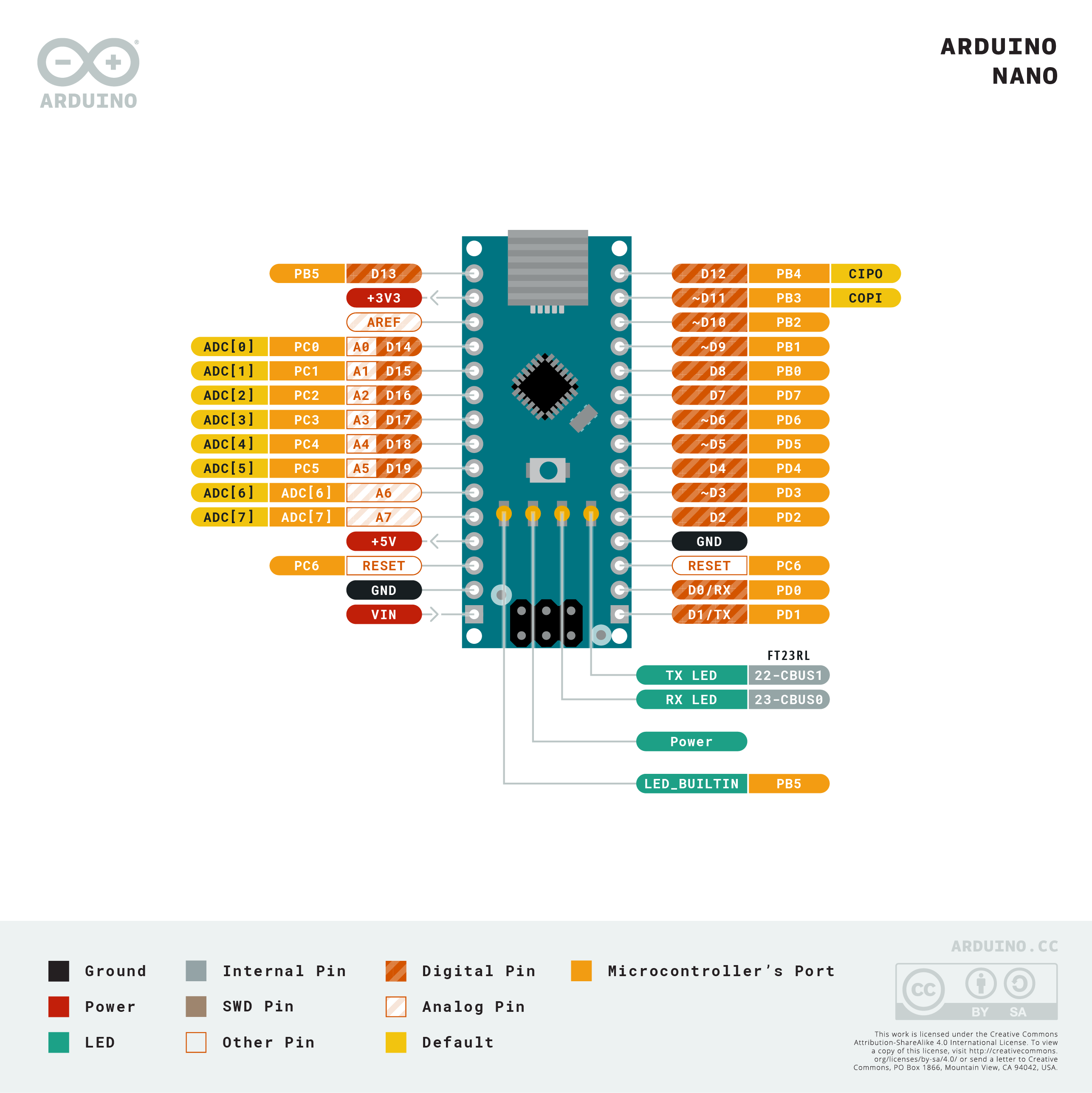
On the Arduino Nano, the I²C pins are on the analog header — the same A4/A5 as the Uno, but with different physical pin numbers on the board’s edge connector. Looking at the Nano’s physical headers: A4 is physical pin 13, A5 is physical pin 14. It’s easy to wire to the wrong location if you’re counting from one end.
Arduino Nano A4 (SDA, physical pin 13) → LCD SDA
Arduino Nano A5 (SCL, physical pin 14) → LCD SCL
Arduino 5V                             → LCD VCC
Arduino GND                            → LCD GND
The I²C LCD backpack includes onboard pull-up resistors, so no external pull-ups are needed for a single device.
HC-SR04 sensor pin assignments
Four sensors — front-left (A), front-right (B), left (L), right (R) — each need a trig and echo pin. The Nano has digital pins D0 through D13, but D0 and D1 are hardware serial (RX/TX), so the preference is to avoid them. Starting from D2:
| Sensor | Trig | Echo |
|---|---|---|
| Front-left (A) | D2 | D3 |
| Front-right (B) | D4 | D5 |
| Left (L) | D12 | D13 |
| Right (R) | D0 | D1 |
A note on D6/D7: the original plan was to put the left sensor on D6 (trig) and D7 (echo). During wiring, those jumpers ended up going to D12 and D13 instead — double-checking before powering on caught this before it caused mysterious behavior in the code. Always verify pin connections against your final list before the first power-up.
D0 and D1 are used for the fourth sensor as a last resort — using the hardware serial pins means the Arduino’s serial monitor won’t work reliably while those pins are driven by sensor signals. Since this robot won’t be using serial output during normal operation (the I²C LCD handles debug output), the tradeoff is acceptable. In a design that relies on Serial.print() for debugging, reserving D0/D1 for sensors would be a problem.
Each sensor’s VCC connects to the 5V power rail; each GND connects to the ground rail. The sensors aren’t all running simultaneously — the code fires them sequentially with a short delay between each — so the current draw is manageable from the Arduino’s 5V rail.
Sensor mounting: velcro over hot glue
Mounting sensors that might need repositioning calls for velcro, not permanent adhesive. Industrial-strength adhesive velcro from a hardware store (Walmart in this case, roughly $6 for a roll) holds HC-SR04s firmly against cardboard without requiring removal tools. The self-adhesive backing grips cardboard well enough that the velcro bond releases before the backing peels.
One practical note: consumer-grade adhesive velcro actually works better for components that get adjusted frequently, since its backing bond is stronger relative to the velcro separation force. Industrial velcro is so strong between hook and loop sides that the backing sometimes peels off the cardboard when you try to separate them. For permanent mounting, either works. For anything you might reposition, consumer-grade is the better choice.
The sensors are mounted on the top deck of the two-story chassis (see the chassis build post), facing outward at the front-left, front-right, left, and right positions.
Power LED
A green LED salvaged from ClusterBot (the earlier robot) with a 56 Ω series resistor connects between the 5V rail and GND, mounted through a punched hole in the chassis. At 56 Ω the LED runs fairly bright — the resistor was sized for a larger-than-standard LED that could handle higher current. For a standard 5mm LED, 220 Ω is the safer choice.
The LED’s purpose is exactly what it sounds like: a quick visual confirmation that the robot has power before you set it on the floor.
Final connection summary
I²C LCD:      A4 (SDA), A5 (SCL), 5V, GND
Sensor A:     D2 (trig), D3 (echo), 5V, GND
Sensor B:     D4 (trig), D5 (echo), 5V, GND
Sensor L:     D12 (trig), D13 (echo), 5V, GND
Sensor R:     D0 (trig), D1 (echo), 5V, GND
Power LED:    5V → 56Ω → LED → GND
With all connections made, the LCD backlight illuminates when power is applied and the green LED confirms the rail is live. The programming step — reading four sensors with staggered timing and displaying distances on the LCD — is covered in the HC-SR04 sensor code post.
References and further reading
- HC-SR04 datasheet — trigger pulse timing, echo measurement, and the 2cm–4m range spec
- Arduino Nano pinout — the physical pin positions for A4/A5 and all digital pins on the Nano header
- I²C scanner sketch — verify the LCD address before writing application code
- Four HC-SR04 sensor code post — the sketch that reads all four sensors with staggered delays and displays distances on the I²C LCD